Building a Synthesizer, 7
Building the Mixer
- Introduction: The World of DIY Synthesizers
- 1: The mki x es.EDU DIY System
- 2: Building the Power Supply
- 3: Breadboarding the VCO
- 4: A Gentle Introduction to Op Amps
- 5: Building the VCO
- 6: The Logic Circuits Model of Computation
- 7: Building the Mixer
- 8: Building the Envelope Generator
- 9: A Field Guide to Oscillators
- 10: Building the VCA
- 11: Debugging Circuits and Software Debugging
- Glossary and Electrical Connections
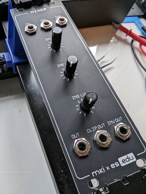
There are two “mixer” modules in the mki x es.EDU system, the “Mixer” module and the “Output” module. Both can combine multiple audio signals into one, but they do it somewhat differently and the use cases are different. This “Mixer” module will combine up to three mono signals into a single mono output, and it can also optinally clip or invert the signal. The “Output” module will combine up to two mono signals into a stereo line level and headphones output, with panning.
A mixer is a pretty handy module to have, and there are different reasons to use a mixer, hence different mixers. You can obviously use this one to blend the two oscillators in the kit, making a hybrid sound with both a PWM and noise sound. But you can also use it, for example, to combine the two different envelope generators, producing one envelope which is far more complex than you could make with just one envelope generator. You could combine a key-triggered and a looped envelope, for example.
Another big difference between the two modules is the directions. The directions for the “Mixer” module were written by Moritz Klein and very much follow the style set out in most of the rest of the mki x es.EDU modules, with an emphasis on breadboarding before soldering, and a folksy style. Moritz frequently says, in both the printed directions and his videos, approximately, “you could use math to calculate these values, but I prefer to use trial and error.” I’ll discuss the Output module in a future post, but for now let’s just say that the directions are day-and-night different. The Output module directions were not written by Moritz and there is math involved. Good thing I enjoy that sort of thing.
This module, however, has directions written by Moritz Klein in his usual style. I like that, too!
It’s All About the Op Amps
It might seem like I don’t have much to say about this kit. You’ll note that this post is far shorter than many of the others in the series. In truth, however, building this kit inspired me to write the chapter on op amps, which is by far the longest post I’ve written. So there is a lot to say, so much so that it took an extra post.
The mixer module is a very simple introduction to op amps, which gives just a couple of use cases. If you’d like to know more, I’ve got you covered.
Passive vs. Active Mixing
The instructions make a valiant attempt to explain how the mixer works in its final configuration, when it uses an op amp in an inverting configuration. It mostly succeeds, but I do think portions of it could be clearer, so I will attempt to add some additional explanation.
The instructions take us through three steps:
- A passive mixer
- An “active mixer” with an op amp in a non-inverting configuration
- An active mixer with an op amp in an inverting configuration
Passive Mixers, and Why They’re Not So Great
The manual correctly identifies low output volume of the signal (caused by a high output impedance) as one problem with the passive mixer design. But it’s not the only problem. One of the problems with a passive mixer is that if you have a musical signal connected to one of the inputs and then you connect a 0V signal into another input, the level of the music on the output goes down! This sort of makes sense as the new level is the average of the signal and the 0V input, but it’s not what any musician would actually want!
Also about that output: Due to the lack of any kind of buffer, the amount of current in this circuit will change quite a lot depending upon what you have connected to it.
It’s even worse when you have more than two inputs. If you have three inputs, and you have two of them connected to music inputs, and you set the levels appropriately, then you will be very surprised when you plug in a third input and the levels change relative to each other.
Why? A passive mixer is just a voltage divider in disguise. And it’s not much of a disguise. A voltage divider with one input connected to ground is a regular voltage divider, whereas the same circuit with the same input entirely disconnected is just a single resistor. End users of your mixer will not expect this behavior.
Still, you will sometimes see passive mixers advertised as “summing mixers” and all sorts of audio fairy dust attributed to them, at a high price.
“Active” Mixers (with Scare Quotes)
Klein introduces the notion of an “active” mixer by putting a op amp buffer in non-inverting mode after the passive mixer. While this is “active” in the sense that it contains active components, namely the op amp, it’s not what most people would consider an active mixer, because the mixer itself is still passive.
In other words, using a non-inverting op amp configuration passively mixes the two (or more) signals, and then actively buffers the result using the op amp.
To be honest I’m not sure why you would use this configuration, because it doesn’t fix the problems caused by the passive mixer. But it does provide one advantage, namely that plugging in a random module to the output can’t change the behavior of the mixer, due to the op amp acting as a buffer.
Active Mixers (No Scare Quotes)
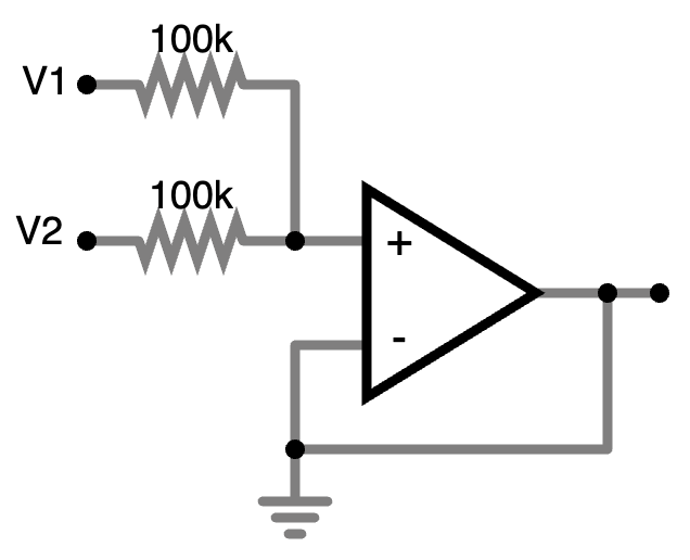
When you swap the non-inverting op amp for an op amp in an inverting configuration, however, things change. Naïvely, this shouldn’t make a difference, because what good does inverting the signal do?
But we’re not just inverting the signal, we are also moving the op amp’s
feedback signal from the op amp
input which doesn’t take the mix output to the one which does. And that is
what makes the difference. In an inverting configuration the op amp must emit
a voltage to bring its - input down to zero, hence the opposite voltage as its
input(s). Because the op amp is always working to keep its - input at zero, it
exactly balances the signal from all of its inputs (labeled V1 and V2 in
the schematic at right).
This means that if you have just one input connected at V1 then the op amp will emit at its output the exact opposite of that signal; it’s an inverter. It will do this whether you have no connection at all at V2 or if you have a wire connected at ground level, carrying no audio signal. If you have two or more inputs connected, say an audio signal on V1 and V2, then the op amp will emit exactly the opposite of their sum.
I wrote about this in my op amps post.
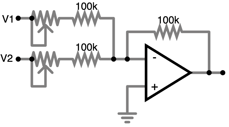
However, although the inversion is inaudible with audio signals, if you’re using the mixer with a lower-frequency signal such as an LFO or some envelope generators then you might notice the inversion. So the next step is to add another inverting op amp to fix the inversion. Klein also adds an ouput for the inverted signal in case you want that.
Distortion
The last bit added to the circuit is a diode distortion circuit, which adds a small bit of distortion to a dedicated output in case you want that. The circuit is essentially two diodes and a trimpot, and there’s an op amp to bring the level back up to match the other outputs.
We think of diodes as “one way valves” for current, but they don’t open linearly, and the distortion circuit exploits this nonlinearity to produce a distorted sound that can be pleasing in some cases.
I’m not sure why the distortion level is set with a trimpot instead of a regular front-panel potentiometer; this is the sort of control which you might want to change for different synthesizer sounds, and having to remove the module from the rack and adjust the clip threshold with a screwdriver is going to discourage that.
Building the PC Board
Well there was no drama here at all. I soldered on the components and everything just worked. No complaints there!

But there was…
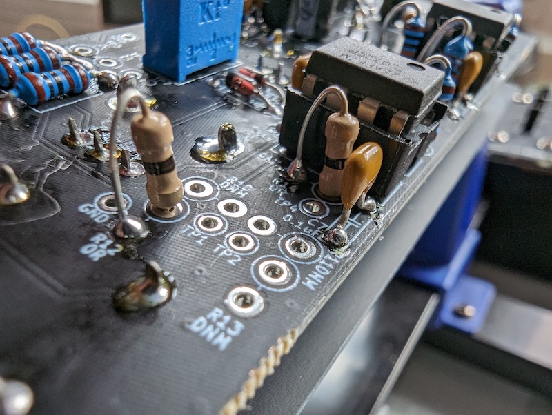
That One Weird Thing With the Zero Ohm Resistors
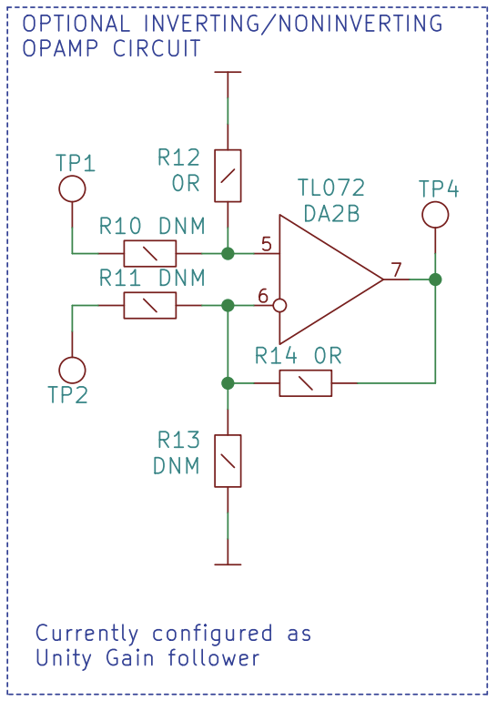
The kit includes two zero Ohm resistors, which really are a thing. That’s a little unusual, but what’s truly strange is that they’re totally unmentioned in the manual, and omitted from the bill of materials. They are are in the schematic (see image at right) and in the pictures of the completed board in the directions. They are part of an “optional inverting/noninverting op amp circuit” which is not in the signal path of the rest of the mixer. (See schematic at right; R12 and R14 are zero Ohms. The remaining resistors should not be installed at all; “DNM” means “Do Not Mount.”)
Installing the two zero-Ohm resistors puts the second op amp in the second TL072 into a buffer configuration, with the noninverting input set to ground. This is the correct way to set up an unused op amp.
I think the purpose of the zero Ohm resistors is they could be removed and replaced with a different value resistor, along with mounting additional resistors in the “DNM” positions, if you later decided to use the additional op amp for… something. They are a wire which happens to be shaped like a resistor, and hence useful when you might want to replace them with a real resistor in the future.
Thanks for reading!
Resources
Instructions
Product Pages
Simulations
All of these simulations are by Moritz Klein
- A simple “active” mixer (passive mixer with an op amp output buffer)
- “Inverting” mixer (an active mixer with an op amp in an inverting configuration)
- “Double negative” mixer (has another inverting op amp to allow for a non-inverting output)
- “Adjustable” mixer (has adjustable input levels, plus inverting and non-inverting outputs)
- Entire circuit (as breadboarded, adds diode clipping)
Videos
- Introducing the mki x es.edu DIY S&H/Noise and Mixer kits, by Moritz Klein (3:57)
- Designing a 3-channel mixer with diode distortion from scratch by Moritz Klein (26:38)
Web Sites
- Mod Wiggler thread (Pretty empty when I looked)
- ModularGrid page