Building a Synthesizer, 10
Building the VCA
- Introduction: The World of DIY Synthesizers
- 1: The mki x es.EDU DIY System
- 2: Building the Power Supply
- 3: Breadboarding the VCO
- 4: A Gentle Introduction to Op Amps
- 5: Building the VCO
- 6: The Logic Circuits Model of Computation
- 7: Building the Mixer
- 8: Building the Envelope Generator
- 9: A Field Guide to Oscillators
- 10: Building the VCA
- 11: Debugging Circuits and Software Debugging
- Glossary and Electrical Connections
What Even Is a VCA?
If you have used keyboard/desktop style synthesizers but not modular synths, you may have seen a “VCA” section of your synth before, or, depending on the synth in question, you may have just seen a dial somewhere with a different label.
A VCA allows you to use one control voltage to adjust the level of another signal. The most common use is to use the output of an envelope generator to adjust the level of the VCO’s output (turning an unchanging drone into a note with an attack, decay, etc.). But there are many other uses for a VCA!
Still, because the two uses above are so common, in many synthesizers the “VCA” is represented as a “Volume” knob somewhere, or as a slider by an envelope generator.
For example, here are two synthesizers with two different labels for the same feature:
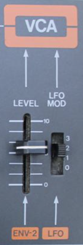
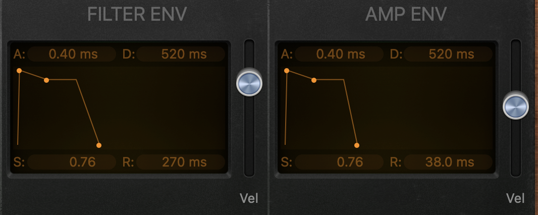
On the left is the “VCA” section of the Roland Jupiter-8. You get two controls: A simple level slider, and a four position switch which controls how much one of the synth’s LFOs affects the output. On the right is the Retro Synth plugin from Logic Pro; here the “VCA” feature is just sort of implied by the envelope and a slider labeled “Vel” (for Velocity) to the right of the two envelope generators. Neither of these have a “control (voltage) input,” because they are hard-wired to the envelope and the LFO, in the case of the Jupiter-8, and to the envelopes, in the case of Retro Synth.
In the modular world it’s pretty common for a VCA to be a separate module, but you may end up using them in exactly the same way: You want to turn the endless drone of a VCO into distinct notes, so you connect an Envelope Generator to your keyboard’s Gate output and you connect the output of the EG into the control voltage input of a VCA. You then connect the VCO’s output into the audio signal input of the VCA, and the output of the VCA now has distinct notes when you press a key. Success!
However, a VCA can be used for other applications; I’d recommend watching this video (particularly the last two thirds) if you’d like to see examples.
How a VCA Works
A VCA is simply a volume knob which can be controlled using a control voltage. The control voltage is “…typically from -2.5 V to +2.5 V (5 Vpp) for LFOs, and from 0 V to +8 V for ADSRs,” to quote the Eurorack (non-)specification. There’s usually two “volume knobs,” in series: A real volume knob you can set with your fingers and an electronically controllable volume setting you set with a control voltage.
We know how potentiometers work, and the “real” volume knob is just one of those, with an op amp for isolation and gain. But how does a control voltage controlled volume knob work? If we ccould find such a thing as a “voltage controlled resistor,” that would do the trick. It sounds like something which could be done with an op amp, but it would require a somewhat less common circuit, called an operational transconductance amplifier (or OTA) instead. These tend to have an amplifier bias or IABC input which will control the gain of the amplifier based on the current going into that input. But other designs are possible, and as we will see the MKI x ES.EDU VCA is based on individual transistors instead of an integrated circuit like an OTA.
Breadboarding the VCA
Before I start breadboarding I ususally separate out the various resistor values, set them in order, and tape them to a piece of paper with their values in Ohms written alongside them.
Important: Before you start breadboarding, carefully look at the 10k, 20k, and 100k resistors. There are two different kinds! See the section “Resistance is Futile,” below, for details. The manual does not include this distinction in the Bill of Materials nor mention it at all unitl much later. You will want to keep these two types of resitors separate, as it will make your life easier later on.
Breadboarding the Volume Potentiometer
The first thing we are asked to build is a volume control using just a potentiometer. Not exciting, but the idea is that a VCA will essentially be just controlling volume using a control voltage instead of a knob. Of course the truth is somewhat more complex, given the need to isolate modules from each other in terms of impedance, but we’ll get there. Anyway, having built that we can verify that we can indeed vary the volume of a signal passing through our not-quite-yet-voltage-controlled-amplifier by twisting the potentiometer knob. Moving right along…
How a Bipolar Junction Transistor Works
If you look up a Bipolar Junction Transistor on Wikipedia or in many electronics books, the description will start with a discussion of “P-type” and “N-type” semiconductors, and at the end you still won’t have a good idea of what they do. Instead, I’m going to go with what Professor Aaron Lanterman calls the “magic elves theory,” and describe what they do without explaining the physical implementation, instead saying, “they do it that way because the magic elves inside make it happen.” This is actually similar to the “transistor man” presentation in Horowitz and Hill’s The Art of Electronics.
The purpose of these kits is perhaps more about teaching you how electronics work than it is about building the greatest synthesizer in the world. We’ve used a couple of transistors in the past, but we haven’t gone very deep into how the work. So, no time like the present! The instructions now take a (pages-long) digression into how transistors, and bipolar junction transistors (BJTs) in particular, work. I won’t repeat that here, but there is a points that I found confusing which I would like to try and clarify.
In the VCO kit we used a transistor as a kind of variable resistor controlled by the base input. The VCA instructions spend a good bit of time explaining why a transistor is not, in fact, a resistor. A transistor provides resistance, clearly: A fairly high resistance value when no voltage is connected to the base! You can control the amount of current passing through the device using the voltage you connect to the base.1
But resistance is not the same as being a good resistor. A transistor is designed to allow current to (easily) flow in only one direction, unlike a resistor, and, also unlike a resistor, a transistor will pass a fairly steady current regardless of voltage applied to the collector. So the transistor is not a drop-in replacement for a resitor, even if it was useful to us in supplying a voltage-controlled resistance when building the VCO. It’s also noteworthy that the VCO required a resistance which varied exponentially with the input control voltage, and thus it’s super convenient to use a transistor, which more or less does just this. With the VCA, however, we want the volume to change linearly with the control voltage, so we will need to be careful about how we use the transistors.
The Problem with BJTs
One problem that BJTs have is that they are not very consistent devices. Even BJTs from the same manufacturer with the same part number will vary in how much current they pass and the precise base thresholds that control the transistor. They will also vary considerably with the outside temperature.
So, we would like to compensate for these variations. How do we do that?
Negative Feedback
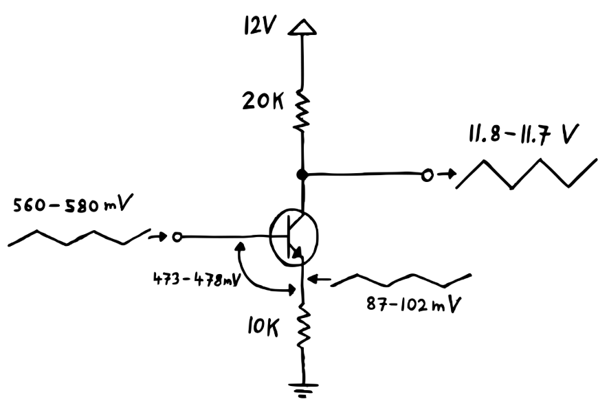
We start with a circuit much like the one on the right but without the 10k resistor at the bottom. Then we get to the point that I found confusing! Moritz talks about “introducing negative feedback” by connecting a resistor between the transistor’s emitter and ground. That’s the 10k resistor at the bottom of the circuit at right. What I didn’t understand was: A resistor is a passive component; how could introducing just one resistor provide any kind of feedback?
The answer is that although the resistor is passive, the transistor is very much not passive, and putting a resistor between the emitter and ground makes a world of difference because it changes the behavior of the transistor. How? When the transistor’s emitter is connected directly to ground then the emitter voltage will always be at ground, no matter what the base of the transistor is set to. But when there is a resistor between the emitter and ground, things get more complicated.
A transistor is “active” when the voltage between the base and the emitter is over a certain threshold, around 0.6V. When the transistor is active, current will pass between both the base and the emitter and the collector and the emitter (for an NPN transistor). This current flowing out of the emitter has to flow across the 10k resostor. When a current flows across a resistor you get a voltage. Therefore the voltage at the transistor’s emitter is no longer being held at ground. Instead it varies depending upon the amount of current passing through the resistor. And this change from “voltage is fixed at ground” to “voltage varies with the amount of current being passed out of the emitter and across the resistor” is the key to understanding how adding just that one resistor can be called “negative feedback.” The more current that passes through the resistor, the higher the voltage difference across its two ends will be, right? However, this means that the end of the resistor connected to the emitter will be at a higher voltage, and therefore the higher the current, the lower the difference in voltage between the transistor’s base and emitter will be… which reduces the current! This is the negative feedback.
Therefore, if something changes the gain of the transistor, such as its temperature, this circuit will have the opposite effect: More amplification means a higher voltage at the emitter which means a lower voltage from base to emitter which means a lower gain!
Another Way to Look At “Negative Feedback”
One of the things that confused me about the directions use of the phrase “negative feedback” is that I hadn’t seen this phrase in other tutorials about transistor amplification. But once I understood what he meant by negative feedback I could line up what he was saying with other explanations. So now I will explain this in a different way, but I will be describing the same “negative feedback” mentioned above. It helps me to have multiple ways to consider the same phenomenon.
In this section I’m summmarizing the explanation from Practical Electronics for Inventors, Fourth Edition, by Scherz and Monk.
The gain of a transistor, by definition, is:
$$ \begin{align} Gain = \cfrac {V_{out}} {V_{in}} = \cfrac {\Delta V_{C}} {\Delta V_{E}} \approx \cfrac {R_{C}} {R_{E}} \end{align} $$
Where VC is equal to the voltage at the collector, RC is equal to the resistance at the collector, and similarly for the emitter. However, that’s not quite the full story, because a transistor has a small internal transresistance in its emitter region, and one way you can think about thermal instability in a transistor is that the transreistance changes with temperature. So a somewhat more accurate model is:
$$ \begin{align} Gain \approx \cfrac {R_{C}} {R_{E} + r_{tr}} \end{align} $$
Where rtr is the transresistance value, which, again, is not constant. This is not 100% accurate as there is some small current flowing from the base to the emitter. But this does tell us that we can minimize the effect of rtr by making RE comparatively large relative to it.
$$ \begin{align} r_{tr} \approx \cfrac {0.026 V} {I_E} \end{align} $$
How much is that? Well, we have IE apporximately 600 μA, which works out to arount 46Ω. So a 10KΩ resistor should make its effects very small indeed. Scherz and Monk say, “In practice, RE should be chosen to place VE around 1 V (for temperature stability and maximum swing in the output). Here we’re around 6V, but note that in the very next step we will be reducing the voltage at the emitter!
Breadboarding a One Transistor VCA
So now let’s build a VCA (with actual voltage control, not just a potentiometer). It looks like this:
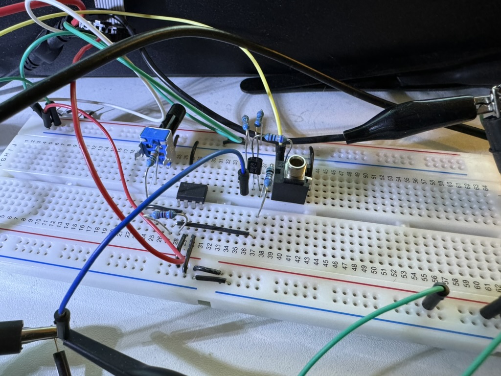
When we look at the output on a scope, though, the results are not so great:
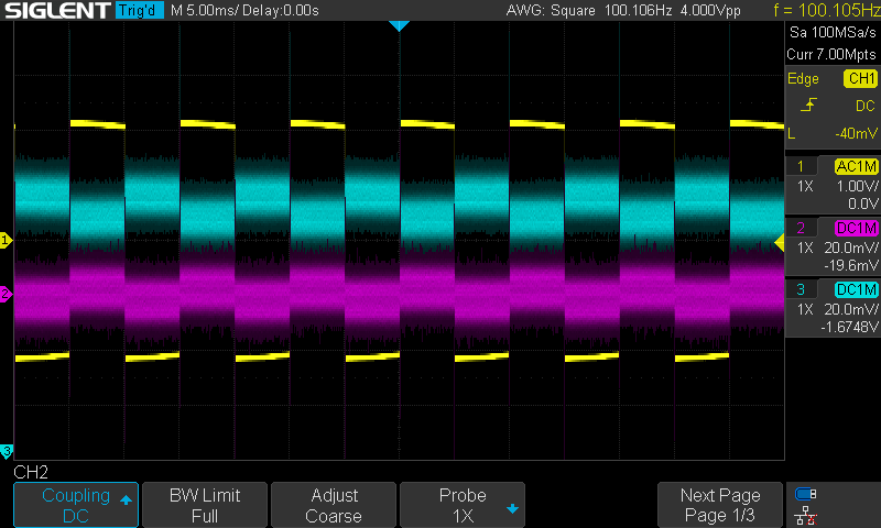
The yellow trace here is the output of a function generator I’m using as my “signal.” This is like the audio signal I would be running through the VCA in the real world. The magenta trace is the input into the base, and the cyan trace is the VCA’s output at the jack. These last two look “blurry,” but note that the vertical scale on the oscilloscope is much smaller for them. (20mV/div vs. 1V/div.)
Breadboarding a Differential Amplifier
There are a few problems with the circuit we have built so far:
- Poor amplification (low gain)
- It’s noisy
- The output is inverted
- It’s still sensitive to temperature variation in the resistors, even though we have improved things by adding the resistor at the emitter
- When we change the CV signal, the DC offset of the audio output changes
Moritz proposes to fix all of this by using a differential pair of transistors. So first we add a second transistor and arrange both in a differential pair.
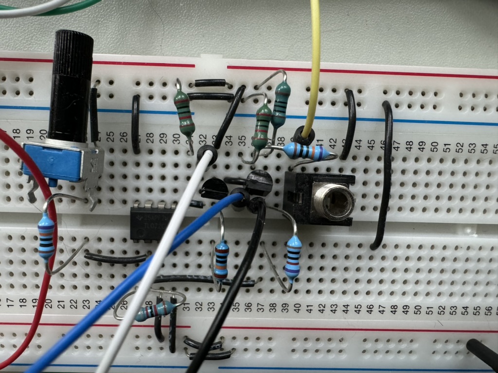
Now we get two outputs, which are in opposite phase:
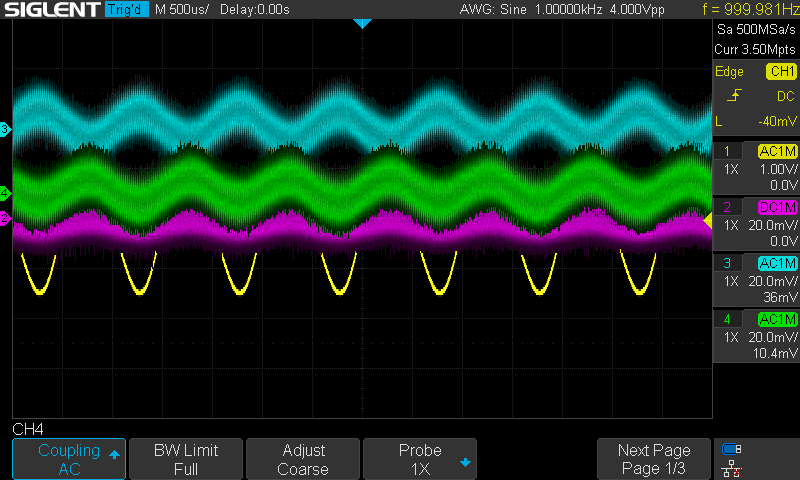
Adding a couple more transistors and the second op amp (in the same IC package as the first one), we can combine the two signals, subtracting them to produce the difference between them (hence, differential pair). This is an op amp configuration which I didn’t show in my op amp tutorial, so here it is:
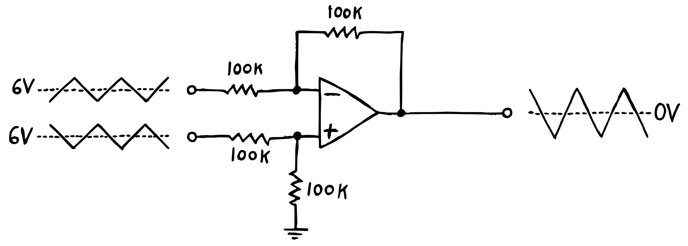
If you’ve read that tutorial, you’ll understand how this works. It’s exactly the same as an inverter configuration, except instead of having the non-inverting (‘+’) input tied to ground, instead the non-inverting input of the op amp is connected to another signal input, via a voltage divider. Without going into too much detail in this post,2 it hopefully makes sense if you think that when the non-inverting input is at ground this is exactly an inverter, because 0/ground minus the inverting input is the opposite of the inverting input.
Anyway, with the op amp outputting the difference of the two transistor signals, our trace now looks like:
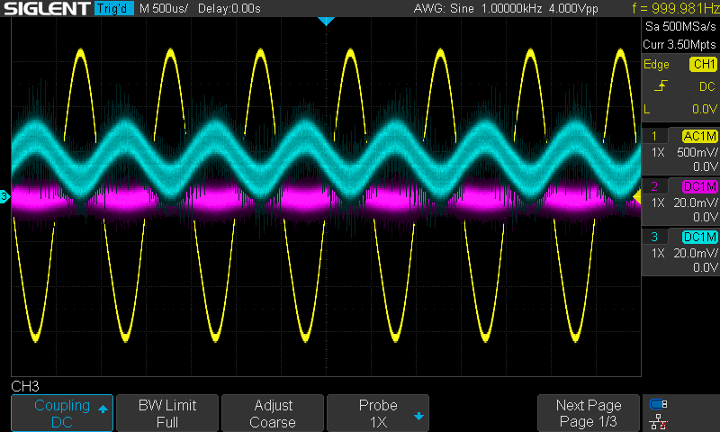
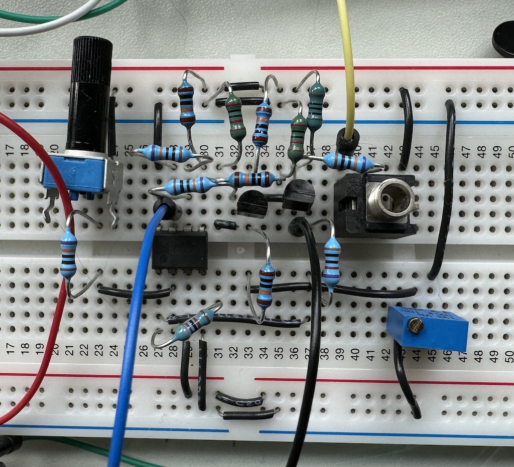
The next step is to add a trimpot which allows adjustment to compensate for small manufacturing differences between the two transistors. Even when both transistors are at precisely the same temperature, two different transistors of the same lot from the same manufacturer may vary in their gain. One way around this is to buy a matched set of transistors in an IC package. Another way around this is to add a trimpot:
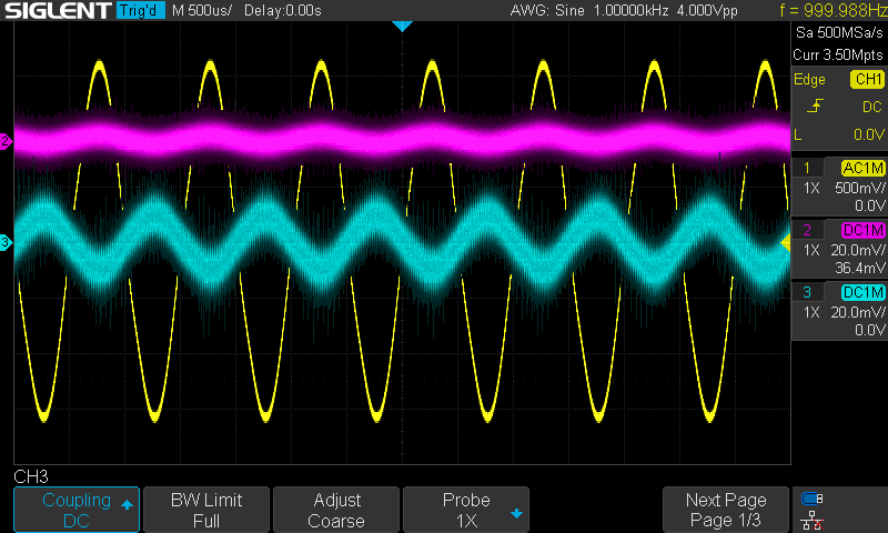
Finally we change some resistor values to make the last op amp in the signal chain boost the amplified signal up to a 10V peak to peak output.
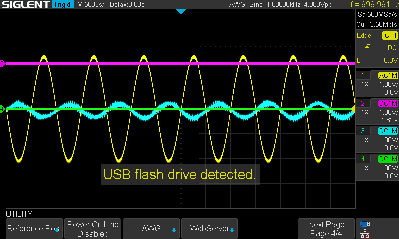
I realize the signal looks quite noisy. Some of that is real, because breadboards tend to be pretty noisy. Some of that is due to the high magnification of the output signal vs. the function generator signal. Here it is with the same vertical scaling:
Soldering It All Together
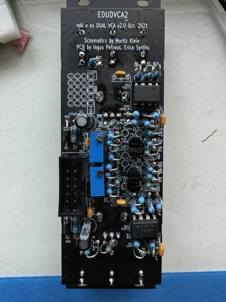
One curious fact about this project is that even though you are building essentially two entirely separate VCAs, they are laid out differently on the PCB. I’m not sure why this is the case; perhaps it has something to do with where the sockets and potentiometers would have landed. But it’s necessary to be very careful when selecting parts, because the layouts are mostly the same, except where they’re different.
Resistance is Futile
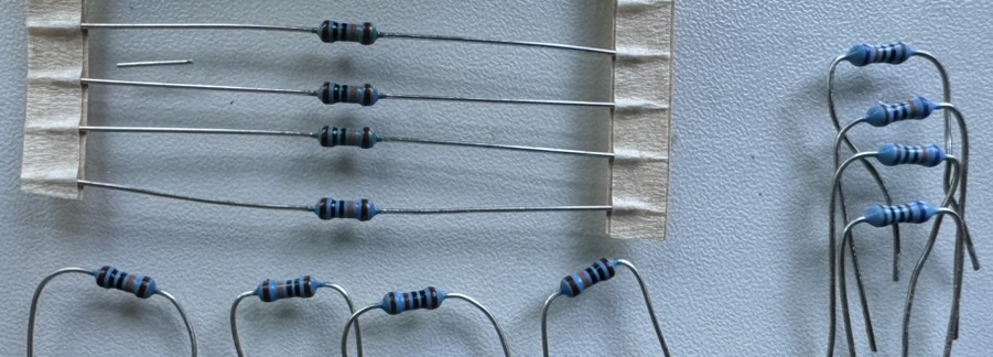
Soldering on the resistors was unexpectedly complicated.
The manual notes that some of the resistors need to be closely matched, and therefore they have supplied a few ±0.1% tolerance resistors where they need to be as close as possible. This is really helpful, but it would have been even more helpful if they had mentioned it prior to page 51 of the manual! As above, I didn’t notice this difference when breadboarding and had to sort out the differently specced resistors.
The manual states:
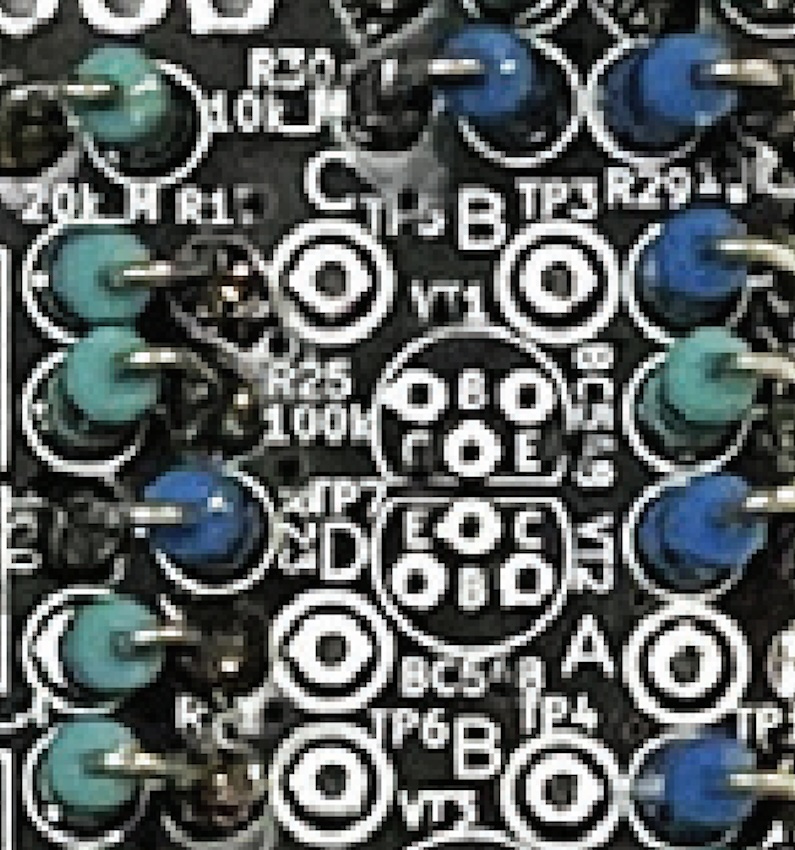
You can identify these ±0.1% tolerance resistors by their light blue bodies [emphasis in original]
There is a difference in the blue, but it’s quite subtle. The ±0.1% and the ±1% resistors look near-identical, and I therefore had a bunch of sorting parts to do from my breadboard assembly (made even more complicated by the fact that 100Ω and 100kΩ resitors also look near-identical when you test them with a multimeter, and their color codes aren’t that distinct, either).
Adding to the “light blue woes,” the colors in the photo in the manual (left, below) don’t match the tolerances in the layout diagram (right)!
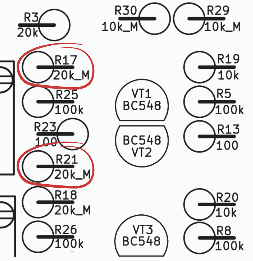
A much better way of distinguishing these different kinds of resistors (unmentioned in the manual!) is the fact that the resistor tolerance is encoded in the color band code. So a 1% tolerance 100k resistor will be “Brown Black Black Orange Brown” whereas a 100k 0.1% tolerance resisotor will be “Brown Black Black Orange Violet”
Choosing Transistors
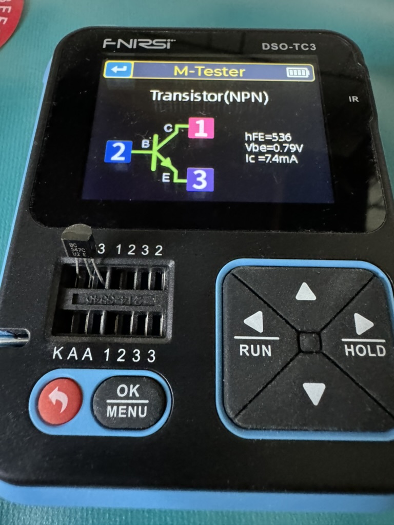
Most of the rest of the soldering was uneventful, but when it came time to attach the transistors I wanted to match them as closely as possible. I have a component tester which I used to measure the hFE of all four transistors included in the kit; their values were 524, 536, 552, and 572. So I paired the 524 & 536 and the 552 & 572 transistors.
Which Way Does the Front Panel Go?
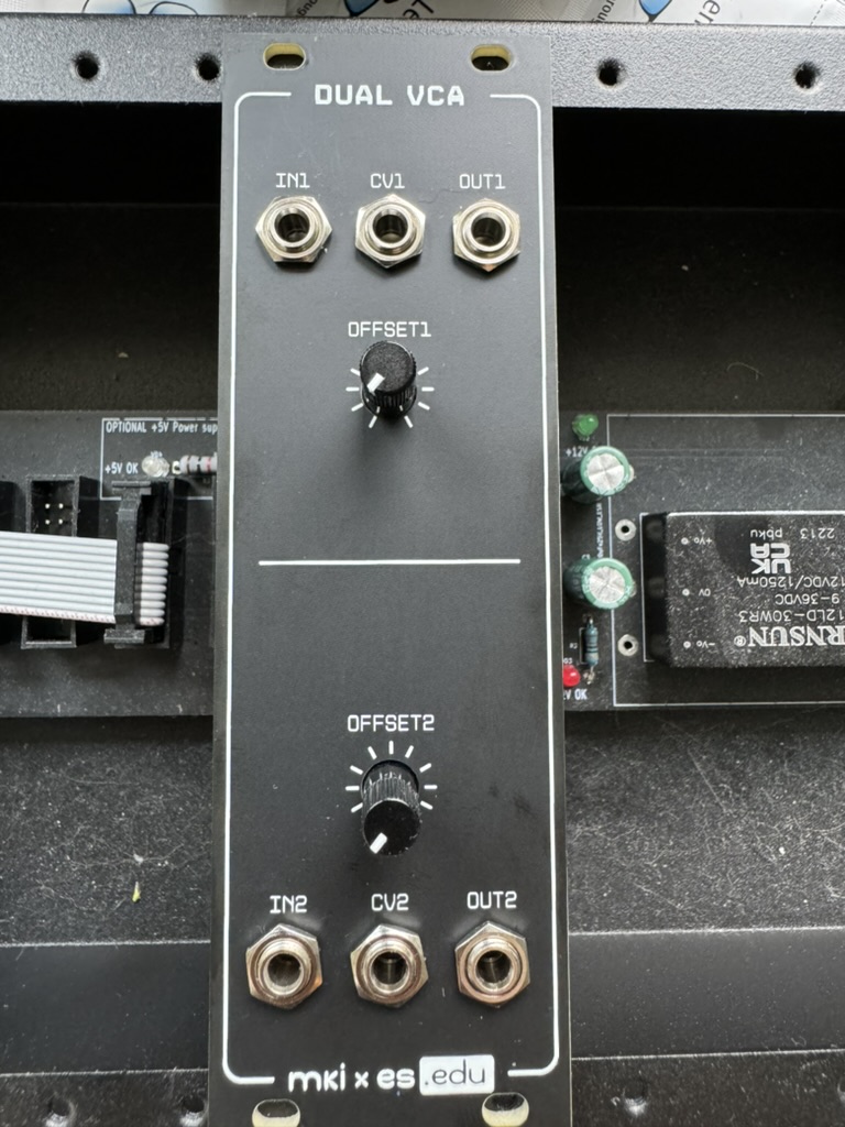
At one point the manual says to attach the front panel, but this kit has two perfectly symmetrical VCAs and there are two possible ways to attach the front panel! Only one way will result in the jacks going into their labeled spaces on the front panel, though (with the “IN1” jack going into the hole labeled “IN1”), so be careful and check the labels on the board when attaching this.
After attaching the front panel, the last step is to insert the two TL072 ICs. I always get a little nervous when I do these, because if you insert them the wrong way you will cook the ICs when you power them up. The two ICs are aligned differently on the board, the photo in the manual is unclear, and the “notch” on the IC doesn’t match the notch on the socket, so you will want to triple-check this before you move on.
Powering Up
Mortiz suggests first testing the VCA using an oscillator (which I have) and just seeing if the “Offset” potentiometers work correctly, so I did that, and it sounded fine. Then you’re supposed to adjust the trimpots to center the oscillation around ground. This is mentioned way back in the breadboarding section of the manual, but it’s important to set your oscilloscope to DC coupled when doing this adjustment. If the trace doesn’t move when you adjust the trimpot then you probably have the oscilloscope input set to AC coupled.
I had to fix a cold solder joint. It took me longer to find than it should have. Hint to future me: If something that used to work stops working, start your search with the jack socket into which you’ve just plugged a cable. One thing that confused me while I was fixing this was a feature I didn’t know the VCA had: IN1 is normalled to IN2, so you can use one input for both VCA sections (and similarly with CV1 & CV2). This is mentioned in the manual, but only in the appendix.
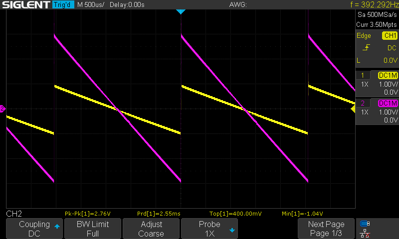
In the trace below, there is a sawtooth waveform from the VCO connected to IN1, and nothing connected to IN2 (so the IN1 signal is normalled to the second VCA). The Offset knobs are set to different positions. The yellow trace is OUT1 and the purple trace is OUT2. I’m pleased that there is far less noise in this (the PC board version of the VCAs) than there was in the breadboard version.
With that finished, I now have a more or less functional synthesizer! There is no filter (yet!), but I can play a note and have an envelope which sounds nice. I’m very happy with the progress I’ve made!
Resources
Instructions
Product Pages
Community
Simulations
All of these simulations are by Moritz Klein
- Voltage Dividers
- Transistor vs. Resistor
- Transistor Amplifiers
- The Emitter Resistor
- Gain Changing Tricks
- The Differential Amplifier
- The Differential Amplifier (with Signal Subtraction)
- The Differential Amplifier (with Mismatch Fix)
- The MKI x ES.EDU VCA
Videos
- Designing a classic transistor-VCA from scratch by Moritz Klein (48:42)
- Introducing the mki x es.edu DIY VCA kit by Moritz Klein (6:19)
- MK1 vs es.EDU Dual VCA - Build and Demo by Quincas Moreira (31:04)
Yes, I said voltage. bipolar junction transistors, despite popular mythology, are voltage-controlled devices. What’s more, I’m not just being pedantic here; this will become important in the discussion which follows.↩︎
Here’s a nice tutorial on using op amps in a subtractor configuration.↩︎